P3317
Exploring for Oil and Gas
The earliest access to oil and gas was through surface expressions. Shallow deposits, along with shallow faulting, allowed oil and gas to migrate to the surface of the land. Societies have accessed oil and gas for millennia. Today, however, almost all commercial oil and gas exploration is from wells many thousands of feet deep.
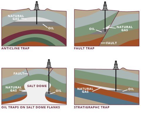
Conventional oil and gas deposits, as opposed to resource plays such as shale oil and gas, are located in permeable rocks, such as sandstone, and are held in place by a trap. A trap is simply a means of preventing further migration of the oil or gas. Four simple traps are illustrated in Figure 1.
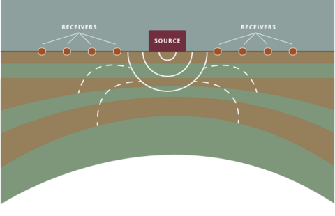
A development team, consisting of geoscientists and engineers, will study the subsurface, consider development options, and make recommendations on the locations and number of wells to develop a particular reservoir or field. One tool that the team may use is a seismic survey. Sound waves are introduced into the ground, and their reflections are recorded at the surface. From these reflections, a “picture” of the subsurface can be developed in much the same way a sonogram is used to look deeply within a human patient. Seismic energy, once applied with dynamite, is more often applied through a truck specially equipped to provide the vibrational energy (Figure 2).
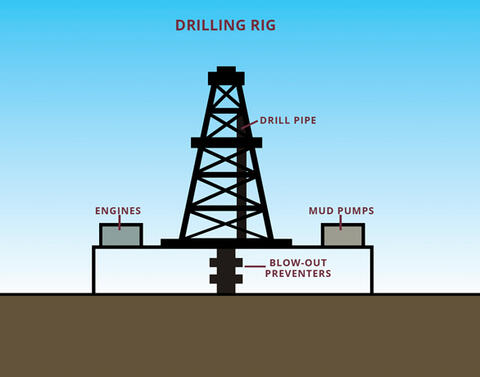
After interpretation of the subsurface survey and creation of an exploration or development plan, one or more wells will be designed. Depending on the development, preparations to drill may be the first activities visible in an area. A location (pad) will be cleared and a drilling rig assembled at the site. Rig operators will drill the well. The most dominant feature of the rig is the derrick, the tall structural piece visible from far away. It raises and lowers the drill pipe, and later, the casing into the well.
The drill pipe is stored in the derrick in “stands” of pipe, usually three 30-foot joints, resulting in 90-foot stands. As the well deepens, more and more drill pipe is needed (Figure 3). Out of sight to those on the surface is the drill bit. It is larger than the drill pipe and creates a hole the diameter of the bit. Drilling fluid, often referred to as drilling mud, is pumped down the drill pipe, past the bit, and back up the circular space between the pipe and the hole. The mud cools and lubricates the bit, cleans the hole of drill cuttings, and provides the hydrostatic pressure to contain all of the fluids in the formation. Mud tanks and pumps, along with equipment to clean and treat the mud, are also on location, along with generators for power. Also in the derrick are a crown block (stationary at the top of the derrick) and a traveling block to raise and lower drill pipe and casing. The rig will also have a means for rotating the pipe, either a kelly or a top drive. Underneath the derrick is the substructure, which allows room for another critical piece of equipment, the blow-out preventer (BOP). If the drilling mud fails for any reason to contain the well fluids, the BOP can be closed to secure the well and allow operators to introduce mud of sufficient density to contain the well fluids. Systems vary, but all contain pipe rams to close and seal around the drill pipe, along with blind rams that will seal off the entire wellbore.
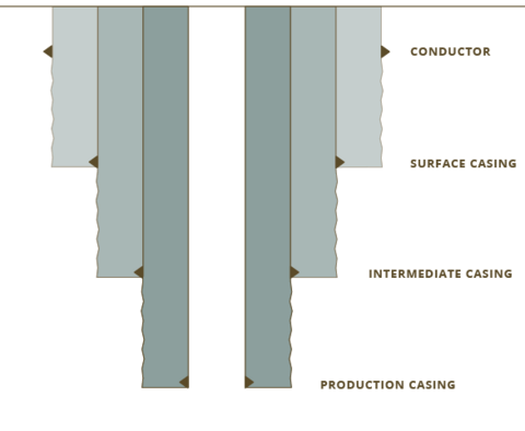
The well itself consists of a series of concentric holes, each isolated by casing (usually steel) and cement (Figure 4). The first, and largest diameter, casing is the conductor, which is structural rather than pressure-containing. It may be driven or cemented in place. Its role is to carry the load of the rest of the equipment used in the drilling process. It is analogous to the foundation of a building. Operators use a bit to drill a hole that passes through the conductor. This first hole section is then cased off with casing and cemented to surface—a process referred to as the surface casing. Its two main roles are to protect fresh water aquifers and to isolate the rest of the well from shallow, weak rocks. After the cement is cured, operators prepare to drill the next hole section. They pressure test the casing and then drill and pressure test a few feet of formation to ensure that the formation is strong enough to continue drilling. Operators drill the next hole section with a bit that passes through the surface casing. This hole may be the last one drilled, or more intermediate holes may be needed, as determined by the well design.
Each additional casing string is run and cemented, with sufficient cement to provide zonal isolation in the well. Cement is usually pumped, much like the drilling mud, down the casing and back up the hole. Additional equipment is run in the casing string to facilitate good cementing.
The final step is the production casing string, which usually penetrates the producing formation. Most often, explosive jet perforations will penetrate the casing and cement and allow access to the formation for treatment and production. In all cases, the casing is cemented to seal and separate the producing formation from other intervals in the well. For all casing strings, Mississippi Oil and Gas Board rules require the prevention of fluid migration out of zone and/or into sources of drinking water.
Hydraulic Fracturing
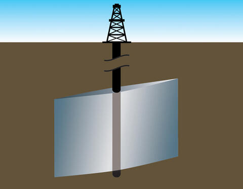
A hydraulic fracture occurs when the fluid pressure exceeds the fracture initiation pressure of the rock. Such fractures can occur naturally. In oil and gas production, hydraulic fracturing can occur when fluid is pumped into a well at sufficiently high pressure, due to low rock permeability, to crack the rock open. Proppant (sand or man-made materials) is pumped into the cracks to hold them open. The resulting flow path is preferable to the well fluids, resulting in a stimulated (higher flow rate) well (Figure 5).
The first hydraulic fracturing treatments were performed by Stanolind Oil and Gas in 1947. The process was then commercialized by Halliburton in 1949. In 2010, the Society of Petroleum Engineers estimated that 2.5 million hydraulic fracture treatments had been performed worldwide, with more than a million in the U.S. alone.
Most conventional treatments consist of the following stages. First, operators pump a pad, which is the base hydraulic fracturing fluid with no proppant added. Hydraulic fracture treatments of conventional reservoirs typically use a fluid that is gelled (viscosified) with an organic starch, generally a guar-based fluid. Shale oil and gas plays often use low-viscosity fluids known as slick water, which has polymers added to reduce friction rather than to carry large proppant loads. The pad has two basic purposes: (1) it creates the hydraulic fracture; and (2) it controls fluid loss to the formation so that the fracturing job can be carried out efficiently.
The next stage or stages contain the proppant. In conventional fracturing, the designer will usually build what is called a ramping schedule, beginning with low concentrations of proppant and building to the final, higher proppant loading. This schedule helps ensure that coverage of the fracture with proppant is complete and as even as possible. The productivity increase from the hydraulic fracture depends on achieving the desired proppant loading in the fracture. The final stage is the displacement stage (i.e., pushing the wellbore). the proppant-laden fluid down to the formation and leaving clean fluid in the wellbore).
The key to a good hydraulic fracture treatment is obtaining a high permeability path through which well fluids can travel into the wellbore. There are various proppants, from sand to ceramics and bauxite. For the most part, the designer chooses the lowest-cost proppant that will deliver the needed conductivity. At high earth stresses, sand grains may be crushed and lose permeability. In those cases, the designer may opt for the more expensive man-made proppants.
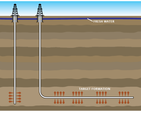
In conventional reservoirs, shale provides the reservoir seal due to its extremely low permeability. In shale plays, however, hydraulic fracturing is often used in combination with horizontal wells to unlock these very tight rocks (Figure 6). Mitchell Energy pioneered this completion method in the 1980s and 1990s in the Barnett shale in Texas. Since that time, this technology has spread to the Marcellus shale in Pennsylvania, the Haynesville shale in Louisiana, the Bakken shale in North Dakota, and others. This completion method offers several important advantages to both the operator and the community. Most importantly, it allows development in formations that would not otherwise be commercially developed. It also allows development with fewer wells. Consequently, it allows development with a smaller surface footprint. That is, more oil and gas resources can be accessed with less land.
Well Integrity and Fracture Containment
Every well should be designed to isolate the producing formation from all other formations and to isolate and protect usable, quality groundwater. Additionally, every well should be designed and constructed to meet fracturing load requirements, usually the highest loads the well will see in its lifetime. The American Petroleum Institute (API) issued Recommended Practice RP 100-1 to give guidance for well planning, construction, and assessment of barriers to flow, cementing, and fracture design. Two of these recommendations directly impact landowners.
First, the API recommends that groundwater be sampled in the area that could be impacted by drilling and hydraulic fracturing operations. See the environmental aspects section below for more detail. The purpose is simple: to establish a baseline level of various dissolved solids present in the groundwater before any drilling and completions are carried out at the location. This baseline makes it easier to determine whether future contamination occurs. The process requires the landowner to voluntarily allow sampling of their water. The oil and gas operator should always provide the analysis to the landowner.
The second recommendation is to identify potential hazards within an area of investigation. The operator should define an area of investigation based on potential hazards from existing and legacy wells, geological differences, and the direction, height, and length of fracture growth. In other words, the operator should define an area where any potential paths exist for loss of containment of fracturing or well fluids. In areas where there are few existing wells and little faulting, this process is straightforward. In other places, such as Pennsylvania, where there are wells dating back to the 19th century and much faulting, the process is more difficult. In either case, landowners may be asked if they know about any old wells, surface expressions of oil or gas, or any other information that may help define potential hazards.
Environmental Aspects
Every oil and gas operator should have a plan that addresses environmental protection. This process begins while the exploration or development is still in the planning stages—before a well is ever drilled. A few key aspects of the API’s RP 100-2 are highlighted in this section.
Site Selection
Well sites are naturally chosen in locations that allow access to the desired oil and gas resources deep in the earth. However, there are also important surface considerations. Operators should seek to reduce overall surface disturbance. They should minimize surface risks due to topography, wetlands, population, and surface waters. Operators should also address visual pollution from lights and noise pollution from operations. None of these risks can ever be completely eliminated, but they can be managed in a manner that protects both the environment and the economic interests of the operator.
Spill Prevention
The site plan should also include a spill prevention and mitigation plan. For example, the layout of the site, housekeeping practices, and inclusion of retaining walls will protect the environment from spills.
Baseline Groundwater Monitoring
API recommends that oil and gas operators prepare and implement plans for baseline groundwater monitoring, which requires permission from landowners. Operators and landowners should recognize that there are not fixed amounts of dissolved elements in groundwater. There are natural fluctuations due to rainfall and other factors. However, operators should still choose a number of sites at various locations to sample. These choices depend on such factors as groundwater flow gradient, depth, distance, and site-specific hydrology.
Reporting
With the rapid increase in hydraulic fracturing that accompanied the development of shale oil and gas came an increased public desire for more information about chemicals used in fracture treatments. In 2011, the Ground Water Protection Council and the Interstate Oil and Gas Compact Commission developed a platform called FracFocus for disclosing what chemicals are used in hydraulic fracturing. At the time of this writing, more than 230,000 wells have been reported via this database. Twenty-three states, including Mississippi, either require or allow companies to disclose chemical data via FracFocus. Mississippi Oil and Gas Board rules require disclosure of fracturing chemicals via Form 3 (completion report) but allow Form 3 chemical reporting to be accomplished via registry with FracFocus.
Publication 3317 (POD-05-25)
Reviewed by Rachael Carter, PhD, Extension Specialist II, Extension Center for Government and Community Development. Written by David Cole, Instructor, Chemical Engineering.
The Mississippi State University Extension Service is working to ensure all web content is accessible to all users. If you need assistance accessing any of our content, please email the webteam or call 662-325-2262.
Download

P3317
Exploring for Oil and Gas
337.86 KB
Departments
Authors
-
 Extension Specialist II
- Ext Ctr for Government & Comm Devel
Contacts
-
Extension Specialist II
- Ext Ctr for Government & Comm Devel