P3539
Irrometer Watermark Series: Location Selection
This publication series provides information and recommendations pertaining to the Irrometer Watermark 200SS, a granular matrix sensor commonly used in Mississippi for scheduling irrigation. Future publications will discuss other types of soil moisture sensors. Users should choose tools that best fit their needs.
Introduction
Where sensors are installed affects the likelihood that the readings are suitable for irrigation scheduling. This publication provides a step-by-step guide to selecting an appropriate sensor location for a field.
Representative Area
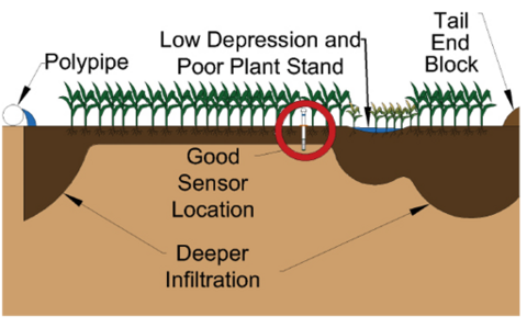
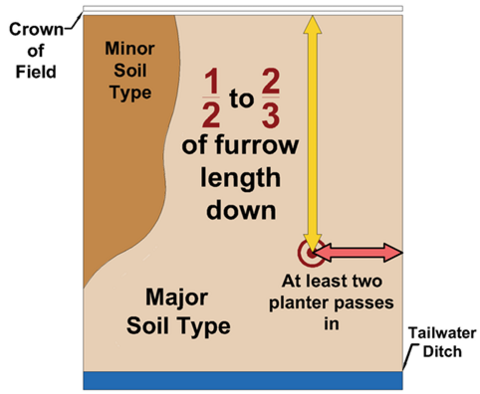
The first step is choosing a representative area within the field. Such an area can be identified based on past experience and observations, along with soil, yield, and aerial maps. The table below suggests criteria for consideration and the associated reasons.
|
Recommendation |
Reason |
|
Place sensors in an area with the major soil type, typical terrain, and average yield. |
Avoid making irrigation decisions based on abnormal areas. |
|
Place sensors ½ to 2⁄3 of the way down the furrow. |
Avoid over-wetted areas near the crown and the tail end of the field. |
|
Place sensors at least two planter passes inward from the field edge. |
Avoid edge effects (e.g., tree lines, pesticide drift). |
Ideal Crop Rows
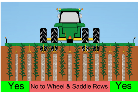
The second step is choosing a crop row that is least disturbed by field operations. Installing in a swing row minimizes the risk of sensor damage by tractors and implements. Also, wheel traffic produces compacted, “hard” furrows, which infiltrate less water than uncompacted, “soft” furrows.
For example, if a field is typically farmed using a tractor with dual rear wheels and 8-row implements, the ideal crop rows for sensor installation would be the first and last rows of each 8-row pass.
Optimal Position from the Row
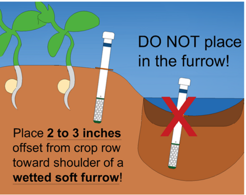
The third step is choosing a position that fairly portrays both crop water uptake and furrow water infiltration. The recommendation is to install the sensors 2 to 3 inches perpendicular from a stretch of healthy, well-spaced plants toward the adjacent wetted furrow.
Sensors placed in the furrow or on the edge of the raised bed may result in centibar readings that are too low. Such positions tend to stay wetter than other parts of the crop root zone.
In contrast, sensors placed in the center of the raised bed may result in centibar readings that are too high if furrow water never wicks to the middle of the bed. This problem occurs more commonly in coarser soils with less lateral water movement.
Suggested Spacing and Depth
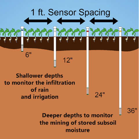
The final step is choosing the exact spots and depths where sensors will be installed. Each sensor should be next to a good uniform plant stand without skips. A sensor spacing of roughly 1 foot apart in the row direction usually keeps the sensors of the same set close enough to reduce potential soil variability but far enough to reduce potential interferences during and after installation. To capture the soil water status of the entire active root zone throughout the season, sensor depths of 6, 12, 24, and 36 inches are generally recommended for each sensor set.
For more information, please contact Extension Irrigation Specialist Drew Gholson at drew.gholson@msstate.edu or (662) 390-8505.
This publication is a contribution of the National Center for Alluvial Aquifer Research (NCAAR), the Mississippi State University Extension Service, and the Row-Crop Irrigation Science Extension and Research (RISER) initiative. NCAAR is supported by the Agricultural Research Service, United States Department of Agriculture (USDA), under Cooperative Agreement number 58-6001-7-001. RISER is supported jointly by Mississippi Soybean Promotion Board, Mississippi Corn Promotion Board, Mississippi Rice Promotion Board, Cotton Incorporated, Mississippi Peanut Promotion Board, and by USDA’s Natural Resources Conservation Service under Conservation Innovation Grant number NR203A750008G007.
The information given here is for educational purposes only. References to commercial products, trade names, or suppliers are made with the understanding that no endorsement is implied and that no discrimination against other products or suppliers is intended.
Publication 3539 (POD-09-24)
By Jacob Rix, former Extension/Research Associate; Himmy Lo, PhD, Assistant Extension/Research Professor; Drew Gholson, PhD, Assistant Professor and Coordinator, NCAAR, and Mark Henry, Extension Associate II, Delta Research and Extension Center.
The Mississippi State University Extension Service is working to ensure all web content is accessible to all users. If you need assistance accessing any of our content, please email the webteam or call 662-325-2262.
